

How Should Electrical Cable and Cable Tray Penetrations Be Fire-Stopped?
October 9, 2026
Fire stopping around electrical cables and cable tray penetrations is critical to maintaining the fire resistance of walls, floors and ceilings. When cables pass through a fire-rated barrier, an unsealed opening can become a pathway for fire, smoke and hot gases. Correctly designed and installed passive fire systems help preserve compartmentation and reduce the risk of fire spreading between areas of a building.
IECC provides passive fire protection solutions for electrical cable and cable tray penetrations, with consideration given to the barrier, penetration configuration and required fire performance. The fire-stopping approach also needs to account for the products used, installation methods and potential changes to cable routes.
The sections below cover electrical penetration types, cable and tray configurations, fire-rated barriers, fire-stopping methods, future cable changes, inspection and common defects.
Electrical service penetrations through a fire-rated wall, floor or ceiling require a suitable fire-stopping solution to maintain the barrier’s required fire resistance. The exact system depends on the barrier, penetration size, electrical components and tested configuration. Generic sealants or foams should not be used where they do not form part of an approved fire-stopping system.
Cable trays and raceways carrying power, data or communications cables can create larger openings through fire-rated walls and floors. The fire-stopping system needs to suit the tray size, cable arrangement, opening dimensions and surrounding fire-rated construction.
Metallic and non-metallic conduits require suitable fire stopping where they pass through rated barriers. Plastic conduits may require intumescent protection that expands when exposed to heat, helping close the opening if the conduit softens or melts during a fire.
Power, control, data, security and fire alarm cables can all create penetrations that need to be sealed. Bundled cables may require a different fire-stopping detail from individual cables because cable quantity, density and opening size can affect the tested configuration.
Busways and bus ducts can create larger penetrations because of their size and construction. Fire stopping around these systems needs to match the casing, opening and fire-rated assembly covered by the tested system.
Some openings contain electrical cables alongside pipes, conduits or other building services. These penetrations require a fire-stopping system tested or assessed for the specific combination rather than treating each service separately.
Recessed electrical boxes, outlets, panels and similar enclosures can affect the fire resistance of a wall or other rated assembly. Depending on their location and construction, additional fire-rated protection may be required around or within the opening.
Cable routes passing through rated slabs or floors beneath raised access floors also need suitable fire stopping. The system should account for the floor construction, opening size and cable configuration to maintain compartmentation.
The required solution should always match the actual penetration and the fire-rated assembly being breached. This helps prevent openings from becoming pathways for fire, smoke or hot gases between compartments.
Cable bundles and trays create larger and more complex penetrations than individual cables. The fire-stopping detail needs to account for the amount, arrangement and type of cabling passing through the opening. Higher cable density can also make gaps around and between cables more difficult to seal correctly.
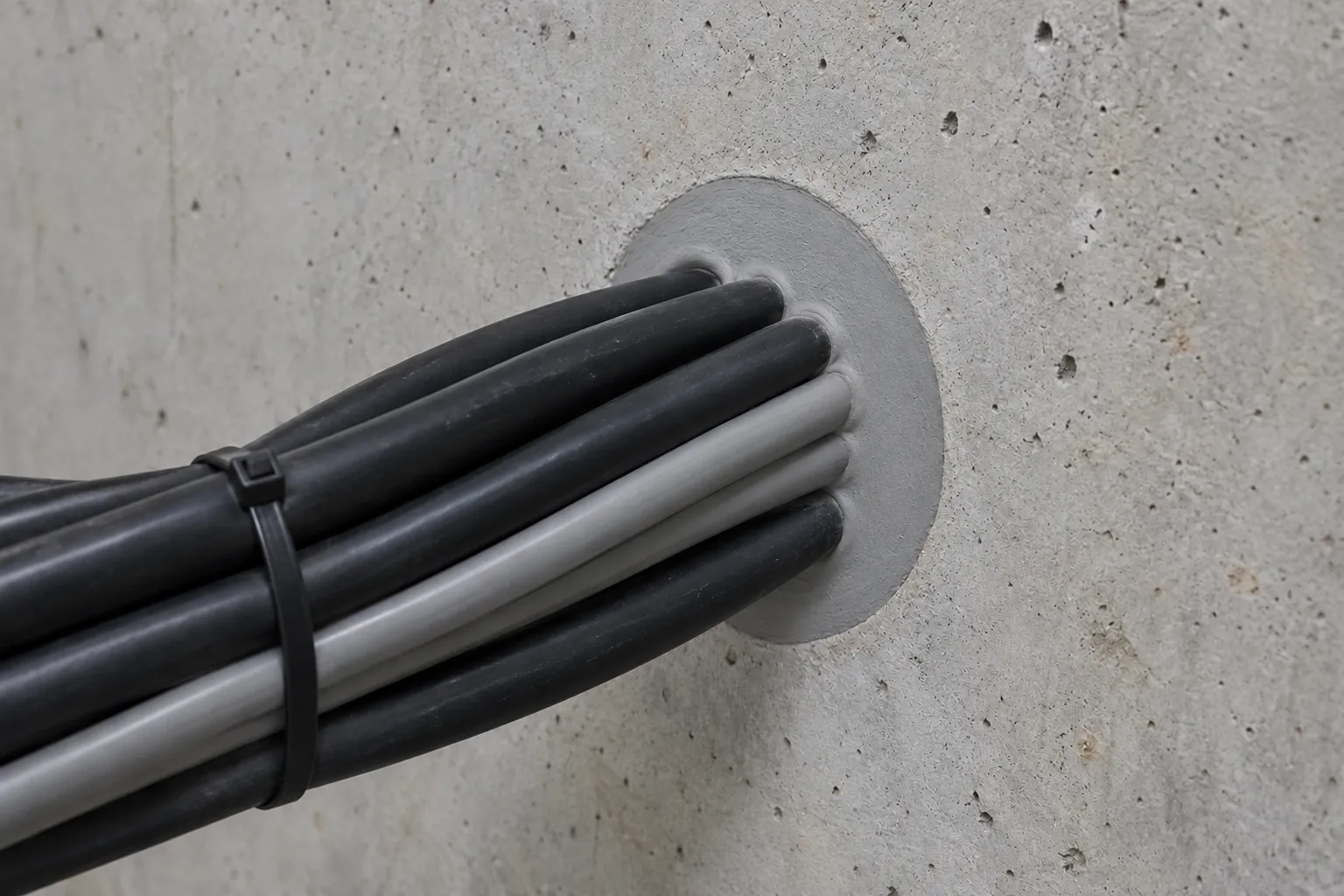
The penetration detail may be affected by:
Any change to the cable bundle or tray configuration should remain within the limits of the tested fire-stopping system. If the cable quantity, type, tray arrangement or opening conditions change beyond those limits, the penetration may need to be reassessed and reinstated using an appropriate tested solution.
The fire rating and construction of a wall or floor directly affect the fire-stopping system required for an electrical penetration. A system tested for a gypsum wall cannot automatically be used in a concrete floor, even when the cable or opening appears similar. The fire-stopping system must suit the specific fire-rated assembly and provide the needed level of fire resistance.
Factors that influence the required system are the following:
The selected fire-stopping solution should match the actual barrier and penetration conditions covered by the relevant tested system. This helps maintain the required fire resistance and prevents electrical openings from compromising the surrounding wall or floor.
Selecting the right fire-stopping product for an electrical penetration depends on the fire-rated barrier, opening size, cable or tray configuration and expected movement. A product suitable for a small cable opening may not provide the required protection for a large bundle or cable tray, even when both pass through the same type of wall.
The selected product should form part of a tested system that matches the actual penetration conditions. This helps maintain the required fire resistance while limiting the spread of fire, smoke and hot gases.
The wall or floor being penetrated must be identified before selecting a fire-stopping system. Concrete slabs, masonry walls, shaft walls and plasterboard partitions can require different solutions, while the system must also provide the required fire rating.
The penetration size, barrier thickness, orientation and construction should remain within the limits of the tested system. A product suitable for a small opening cannot automatically be used for a larger penetration or a different type of assembly.
Cable type, bundle size, tray configuration and opening dimensions all influence product selection. Individual cables, grouped bundles, conduits and trays can require different fire-stopping arrangements.
Larger or irregular openings may require backing materials, mortar, boards, blocks or modular devices rather than sealant alone. Cable density and tray fill must also remain within the limits of the tested system.
Future cable changes should be considered where electrical services are likely to be modified. Re-enterable systems such as fire-stopping blocks, pillows or modular devices can allow cables to be added or removed without unnecessarily disturbing the surrounding fire barrier.
Where relevant, the system should also accommodate the movement covered by its testing so that cables, trays or building movement do not create gaps.
Electrical cable and cable tray penetrations can require different fire-stopping methods based on the barrier, opening size, cable configuration and required fire rating. The selected method should form part of a tested system that matches the actual penetration rather than combining individual products without confirming their compatibility.
Fire-stopping methods for electrical penetrations include:
The appropriate method depends on the specific penetration and the tested system available for that configuration. Barrier construction, opening dimensions, cable type and density, tray arrangement and future access requirements should all be considered before installation.
Fire-stopping around cable trays needs to maintain the fire resistance of the wall or floor while allowing the tray and its supports to perform as intended. Because trays create larger openings than individual cables, the system needs to account for tray dimensions, cable fill, support arrangement and available space around the penetration.
The complete penetration should follow a tested system that matches the tray type, opening dimensions, cable configuration and support conditions. Fire-stopping materials should not simply be packed around the tray based on appearance, as backing, clearances and installation requirements can affect performance.
The cable tray should be correctly positioned and independently supported before fire-stopping begins. The fire-stopping system should not carry the tray’s normal operating load unless the tested system specifically allows it.
The opening should be clean, properly sized and free from debris or gaps. Where the tested detail requires framing, sleeves, boards or other components, these should be installed as specified.
Larger tray openings may require a combination of mineral wool, sealant, mortar, fire-rated boards, blocks or modular devices. Backing materials need to be installed to the specified depth and density, including around tray edges and beneath or between components where required.
The final fire-stopping layer should then be installed according to the tested detail. Sealant depth, compression and curing requirements should be followed rather than adjusted to suit the available space.
Cable trays are often modified as electrical systems expand, so future access should be considered when selecting the fire-stopping system. Re-enterable blocks, pillows or modular transit systems can make cable additions easier without permanently damaging the fire barrier.
Any cable or tray modification should remain within the limits of the tested system. If fire-stopping materials are removed or the cable fill and tray configuration are changed, the affected area should be reinstated using the specified materials and installation method.
Electrical cable routes often change as buildings undergo renovations, tenant fit-outs and system upgrades. Adding cables through an existing fire-stopped penetration can affect its fire resistance if the new configuration falls outside the limits of the original tested system.
New cables should only be added where the existing fire-stopping system allows the change or where a suitable replacement system has been established. Removing fire-stopping materials or adding cables without properly reinstating the system can leave gaps that allow fire and smoke to pass between compartments.
Where future cabling is expected, the penetration can be designed with suitable spare capacity and a re-enterable fire-stopping system. Blocks, pillows and modular transit systems can allow cables to be added or removed without rebuilding the entire penetration.
The system should still be suitable for the expected cable types, opening size and maximum fill. Clear records of the installed system can also make future modifications easier to complete correctly.
Before adding a cable, the existing fire-stopping system should be identified and checked against the proposed modification. The new cable configuration needs to remain within the tested limits for factors like cable type, size and opening fill.
If the change falls within the approved system, the affected fire-stopping can be reinstated using the specified materials and installation method. Any damaged or unsuitable material should be replaced rather than simply covered over.
If the existing system is unknown or the new configuration exceeds its tested limits, the penetration should be reassessed and an appropriate tested solution established before work proceeds.
Fire-stopping for electrical cable and cable tray penetrations needs to follow a tested system that matches the actual installation. Fire tests assess a specific combination of barrier construction, opening size, cable or tray configuration and fire-stopping materials. Changing those conditions can affect how the penetration performs during a fire.
A system that looks similar to a tested detail is not necessarily equivalent. Following the approved system helps maintain the intended fire resistance and limits the risk of fire and smoke passing through the penetration.
Fire-stopping testing covers specific conditions, which can include the following:
Changes outside these conditions can affect heat transfer, material movement and the size of gaps created during a fire. A tested system should therefore not be treated as a recommendation that can be modified on site.
Changes like substituting a fire-stopping product, increasing cable fill or changing the tray configuration can take an installation outside its tested limits. Adding cables after installation can also affect the original system if the permitted capacity is exceeded.
Where a proposed change does not match the existing tested system, the penetration should be reassessed and addressed using an appropriate tested alternative or other accepted technical solution. This helps maintain the connection between the documented fire rating and the protection installed on site.
Electrical penetrations need ongoing inspection because fire-stopping can be disturbed by cable upgrades, maintenance work, building movement or damage. Even a correctly sealed penetration can become compromised if cables are added, fire-stopping materials are removed or gaps develop around trays and supports.
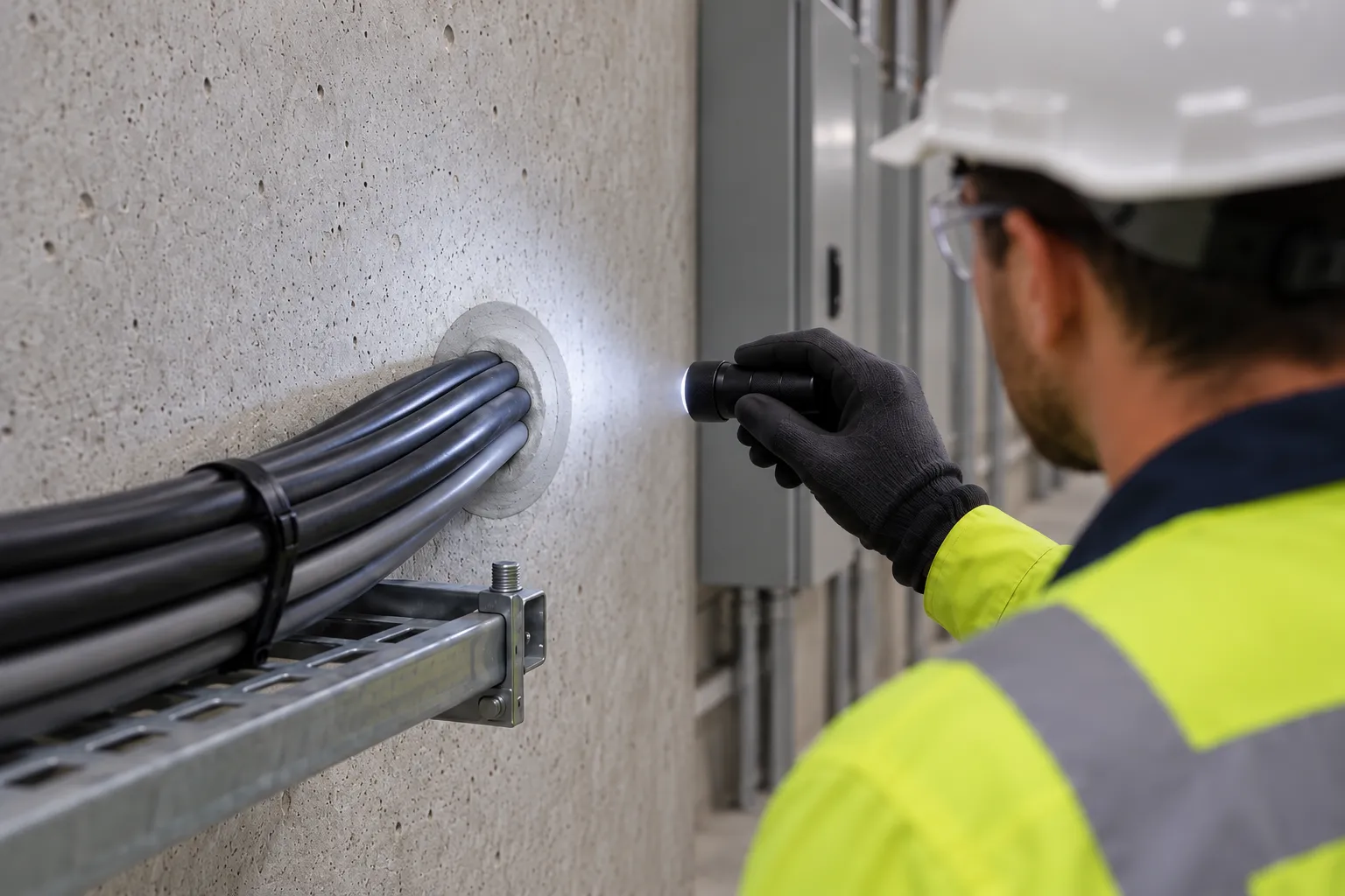
Inspections should confirm that penetrations remain consistent with their approved fire-stopping details. Areas such as service risers, electrical rooms and high-density cable routes may need closer attention because they are more likely to be modified over time.
The building’s fire safety schedules should also be reviewed to identify the applicable fire safety measures and their required minimum performance standards.
Here are some inspection and maintenance steps:
Building owners should also review NSW Government guidance on fire safety maintenance to understand routine servicing requirements for the essential fire safety measures in their building.
Fire-stopping around electrical cables and cable trays can become ineffective when the installation does not match the tested system or is damaged during later work. Common passive fire defects include gaps around cables, insufficient backing, unsuitable materials and modifications that are not properly reinstate
These issues can compromise the fire resistance of the surrounding wall or floor and create pathways for fire, smoke and hot gases. Regular inspection can help identify defects before they affect the performance of the fire-rated barrier.
Gaps can develop around individual cables, cable bundles and tray edges when fire-stopping materials are not installed to the required depth or are disturbed after installation. Cracking, shrinkage or impact damage can also leave parts of the penetration unprotected.
Oversized openings are another concern. If the space around cables or trays is not filled according to the tested system, concealed gaps can remain even when the visible surface appears sealed.
Using products that are not part of the tested system can compromise the penetration’s fire performance. Take these examples:
The product, backing material, thickness and installation method all need to match the approved system for the specific penetration.
Electrical work can create defects when cables are added, removed or rerouted without properly reinstating the fire-stopping. Cutting through an existing seal, increasing cable fill or changing the tray arrangement can take the penetration outside its tested configuration.
Missing labels or records can make these problems more likely because future contractors may not know which system was originally installed. Damaged or modified penetrations should be repaired using the approved system rather than covered with an untested material.
Effective fire stopping of electrical cable and cable tray penetrations is essential for maintaining fire-rated barriers and compartmentation. Selecting a tested system that suits the barrier, cable or tray configuration and required fire rating, followed by correct installation and inspection, helps prevent openings from becoming pathways for fire, smoke and hot gases.
IECC supports the use of suitable fire-stopping solutions as part of effective passive fire systems, with consideration given to the conditions of each penetration and any future cable changes. Ongoing inspections and proper maintenance can also help identify defects or unauthorised modifications before they compromise the intended fire resistance of the building.