

Can I Use a Wall Fire Rating From Either Side?
November 5, 2026
A wall schedule can show a fire-resistance level without making it clear which face was exposed during testing. If you are selecting a wall with different linings on each side, that distinction can affect whether the assembly suits your design. A rating attached to a wall type should not be treated as confirmation that it performs equally in either orientation. For Sydney architects and developers, IECC clarifies the supporting evidence and technical considerations involved in selecting and reviewing asymmetric fire-rated wall systems.
The questions are which direction of fire exposure the design requires, what the available evidence covers and whether proposed changes remain within its scope. Addressing these questions early helps project teams compare wall assemblies, coordinate technical details and avoid discovering fundamental compliance issues after construction has started.
A wall with unequal construction on its two faces may respond differently depending on where a fire starts. Its performance depends on how the complete assembly behaves under the exposure conditions covered by its supporting evidence, rather than simply whether its individual materials are described as fire-rated.
Asymmetric fire-rated walls can be suitable design choices. However, their suitability depends on matching the documented construction and supported exposure direction to the project requirements. A stated fire-resistance level should not automatically be interpreted as applying from either side.
Asymmetry can arise from different numbers of lining layers, different lining materials or protective construction present on only one face. Even when the finished surfaces look similar, the concealed arrangement may differ. An architectural elevation alone provides limited information about whether both faces are equivalent for fire resistance.
The wall's behaviour depends on how its linings, framing, insulation, joints and supports work together. A lining may delay heat reaching the cavity and framing or help maintain the assembly’s integrity. Its position within the wall build-up matters, not just its thickness or product description.
For example, a wall with two layers of plasterboard on one side and one layer on the other has an unequal construction. If its supporting evidence identifies a particular face as the exposed side, reversing the arrangement changes the relationship between the linings and the fire exposure. Keeping the same materials does not automatically preserve the documented performance.
Adding together individual material ratings also does not establish a wall rating. The evidence relates to a defined system with construction details and limitations. This distinction between individual products and complete assemblies is important when reviewing fire-rated materials and their supporting evidence.
Fire exposure heats the exposed lining first. As temperatures rise, the way that lining protects the cavity, framing and opposite face can influence the assembly's performance. Reversing the exposure changes the sequence in which those components are affected.
Not every asymmetric wall necessarily requires two separate physical tests. Depending on the construction and applicable evidence framework, an assessment may address another exposure direction or a defined range of configurations. However, that additional application must have a suitable technical basis rather than relying on assumptions about how the wall should perform.
When comparing proposed wall systems, ask whether the stated performance applies to the intended orientation. The technical submission should allow the project reviewer to connect the proposed room-side arrangement with the exposure conditions covered by the evidence. A generic rating on a product sheet may help with initial selection, but it may not answer this project-specific question.
The answer sits in the supporting documentation, not necessarily in the short wall description on a drawing. A qualified reviewer needs enough information to identify the evaluated construction, the exposed face and the limitations of the claimed application.
Designers and developers should obtain a traceable evidence package and clearly document the intended wall arrangement. Assessing whether that evidence supports the proposed application should involve appropriately qualified professionals rather than an informal check of selected report pages.
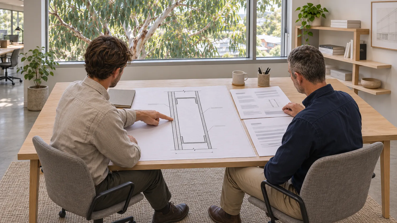
A wall fire test report should allow the reviewer to understand what was actually evaluated. Relevant information can include assembly drawings, lining schedules, framing details, insulation, support conditions and whether the wall was tested under load. The exposed face also needs to be identifiable within the documentation.
The NCC sets out procedures for determining a building element’s fire-resistance level, including requirements for documentation supporting tested construction and certain variations.
Labels such as 'Side A' and 'Side B' are only useful when connected to a clear section drawing. Room names can also confuse when standard details are reused across multiple locations. A reviewer needs to connect each designation with the physical wall build-up and then compare it with the proposed construction.
The reported result must also be considered alongside its test conditions. A headline fire-resistance level may not communicate restrictions relating to height, orientation, construction or other variables. Marketing summaries and report extracts can omit qualifications that affect whether the system is suitable for an application.
A test report is not necessarily the only relevant document. A technical assessment may address variations or applications beyond the directly tested specimen, including alternative exposure arrangements where its scope supports that use.
The distinction is important:
For example, an assessment that supports a specific lining variation does not automatically establish that the wall can also be reversed, increased in height or constructed with a different framing arrangement. Each proposed change needs to fall within the documented scope.
Check that the wall schedule, supplier submission and assessment refer to compatible system versions and construction details. If the evidence uses a different designation, the relationship must be explained rather than inferred. Keep the review outcome associated with the specific wall type and orientation so later drawing revisions do not separate the accepted arrangement from its supporting evidence.
Before deciding whether an assembly's evidence is sufficient, establish which exposure direction or directions the building design requires. This requirement should not be determined by whichever wall system is easiest to purchase or fit into the available space.
The design professionals should establish fire-resistance performance for each location. Wall selection can then be assessed against those requirements, including how its two faces relate to the spaces it separates.
A separating wall sits between spaces with specific uses, layouts and fire-safety functions. These circumstances influence the design requirements, but a room label alone is not enough to establish the required exposure direction. The answer needs to come from the project's documented design basis.
It can be tempting to assume that the space with the more obvious ignition sources is the only side that matters. This may overlook the wall's role in the wider building arrangement or requirements associated with the adjoining space. Conversely, requiring identical performance from both faces without checking the design basis can unnecessarily restrict the available options.
The distinction is between a documented project requirement and an intuitive judgement about where a fire seems more likely to start. The responsible designers should make that distinction explicit. If the requirement differs between otherwise similar wall locations, the drawings and schedules need to preserve those differences.
This is vital when one standard wall detail is proposed for several applications. A system that suits one separation may not automatically suit another, even when both have the same nominal fire-resistance level.
A coordinated wall schedule should identify the required performance and relevant exposure direction, using side designations that can be understood on the plans and sections. This provides a consistent basis for assessing supplier alternatives and proposed architectural changes.
Where the design basis is unclear, refer the question to the relevant fire-safety designer, fire engineer or project professional. The acceptance process may involve further technical review, but it should not rely on a supplier or installer guessing the intended fire scenario.
This distinction between design requirements and product capabilities is also necessary in complex projects. Discussions about performance-based passive fire protection in complex designs are relevant when a proposed arrangement needs more than a straightforward match to an established detail. Such work still requires a clearly defined project objective and appropriate supporting evidence.
Record the exposure requirement where the people selecting, documenting and reviewing the wall can find it. If room uses or separation layouts change during design development, the professionals should revisit the requirement before carrying the existing wall selection into revised drawings.
You may want the thicker or more robust lining on a particular side for durability, finishes or space planning. However, reversing an asymmetric build-up can change its relationship to the required fire exposure.
Treat the proposed reversal as a technical change requiring review. Whether it is acceptable depends on the exact arrangement and supporting evidence, not on how minor the change appears on a drawing.
There is a difference between changing how a wall is drawn on the page and changing which lining faces a specific space. A mirrored section may look like a documentation adjustment while placing the differently constructed face towards the required fire exposure.
For example, consider an assessed wall with two layers of fire-rated plasterboard on one face and one layer on the other. If the evidence identifies the two-layer side as the exposed face, reversing the wall changes which lining encounters the fire first. The total number of boards remains unchanged, but the sequence of protection through the assembly is different.
The same care is needed when a standard detail is rotated or reused across a plan. A wall type name can remain unchanged while its orientation relative to adjoining rooms changes. Without explicit side identification, different project participants may believe they are following the same detail while interpreting it differently.
The reviewer should establish whether the existing test or assessment evidence supports the proposed reversal. If it does not, the next step is to seek technical clarification or consider another supported assembly rather than relying on a verbal assurance that the wall is unchanged.
Give the reviewer a marked-up section showing the current arrangement and proposed alternative, with adjoining spaces identified. Explain the reason for the change and reference the evidence currently supporting the wall. This is a design coordination task, not an invitation to develop an untested modification on site.
The review should also consider whether related details remain compatible. Reversing the wall may affect how a service penetration, opening or junction relates to the exposed face. A satisfactory answer about the main wall does not automatically resolve these interfaces.
Once the change has been reviewed, carry the accepted arrangement through the relevant drawings, wall schedules and technical submissions. Retaining an outdated section in one package can undermine an otherwise clear decision. The people constructing and inspecting the wall need a consistent description of the selected assembly.
If procurement is already underway, flag the issue before materials or prefabricated elements are committed to the revised arrangement. Ask competing suppliers to address the same proposed orientation in their submissions so comparisons are based on supported configurations rather than different assumptions about which side faces the fire.
Evidence supporting the main wall does not automatically establish the suitability of every item connected to it. Penetrations, openings and junctions can have their own construction limits, including conditions related to the supporting wall and exposure’s direction.
For an asymmetric assembly, the coordination task is to check that these details suit the selected wall in its intended orientation. Matching a nominal rating alone may leave important differences unresolved.
A penetration system is evaluated in a supporting construction with specified services and sealing arrangements. Its evidence may identify wall thickness, lining configuration, cavity conditions or exposure limitations. These details need to be considered alongside the evidence for the wall itself.
If a proposed penetration detail was evaluated in a different wall construction, the reviewer needs to establish whether its scope supports use in the asymmetric assembly. A similar overall thickness is not enough to demonstrate that the supporting constructions are interchangeable. The location and nature of the protective linings can matter.
Victoria’s Building and Plumbing Commission provides guidance on documenting fire protection for service penetrations, including checking that the supporting construction, service and protection method match the tested arrangement.
Exposure direction also deserves direct attention. Does the supporting evidence address the required direction or directions for the proposed penetration arrangement? A seal shown at one face should not be assumed to provide equivalent performance when exposed from the other side. Equally, a detail that appears one-sided is not automatically unsuitable. The documentation needs to resolve the question.
Openings and wall junctions introduce further interfaces between systems. Door assemblies, glazing where proposed and perimeter joint systems may each rely on supporting construction and fixing conditions. Their suitability cannot be inferred solely from the rating assigned to the surrounding wall.
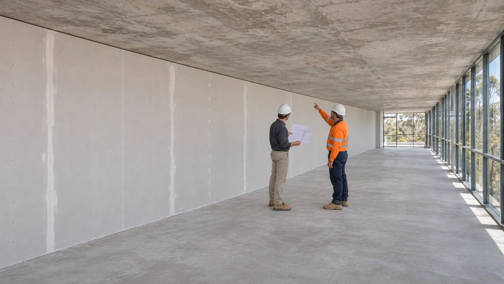
At the wall head, base and adjoining construction, the detail must accommodate the conditions addressed by its evidence. Exposure from the opposite direction may change which part of a joint or protective arrangement is affected first. Any directional limitations need to remain clear when the detail is incorporated into the project.
These interfaces also demonstrate why passive fire defects can affect active fire system performance. A fire separation is part of a coordinated fire-safety design, not an isolated material specification.
Ask for submissions that identify the supporting wall and relevant exposure conditions for each connected detail. Where different specialists supply separate components, nominate the responsible project professional to resolve compatibility questions. Otherwise, each component may arrive with documentation while the relationship between them remains unreviewed.
If the project requires resistance to fire exposure from either side, select an assembly with suitable supporting evidence for both directions. Do not assume that an asymmetric wall is automatically unsuitable or that a visually symmetrical wall satisfies every aspect of the proposed application.
The selection process should connect three things: the required exposure conditions, the exact wall build-up and the scope of its supporting evidence. If any of these remain unclear, resolve the issue before treating the system as selected.
Start by asking suppliers to address required exposure directions explicitly. Their submissions should identify the wall configuration, relevant test reports or assessments and any limitations affecting the proposed location. This makes the comparison more useful than relying on nominal ratings and overall wall thicknesses.
An asymmetric assembly may have appropriate support for exposure from both sides through its available test and assessment documentation. Another assembly may have evidence limited to a particular direction. Neither outcome can be inferred from the number of lining layers alone.
A symmetrical alternative may simplify orientation control, but it still needs to be reviewed against the project requirements. Height, support conditions, loading where relevant and connected details remain part of the assessment. Changing to a different system is not simply a matter of substituting a wall type label.
When comparing options, consider how clearly each assembly can be documented and coordinated. A supported system with unambiguous details can reduce the risk of orientation errors during later design changes.
If the documents do not clearly address both directions, seek specialist review rather than adding lining or reversing components as an assumed remedy. A passive fire consultant can identify the evidence questions that need resolution alongside the relevant designers and other responsible project professionals.
Experts can review the wall sections, required exposure conditions, supplier submissions and proposed connected details. Providing this information helps focus the discussion on whether the documented arrangement is supported, what information is missing and which issues require further specialist input.
Possible next steps include obtaining clearer documentation for the selected system, seeking technical assessment or considering a different assembly with suitable evidence. None of these pathways should be treated as a predetermined acceptance outcome.
Ask for the review findings to identify the specific arrangement considered and any outstanding conditions. If a later revision changes the wall build-up, room relationship or connected detail, refer that change to the responsible reviewer before assuming the earlier findings still apply. The key is to establish the required exposure direction before selecting an asymmetric fire-rated wall and confirm that its complete construction is supported by appropriate evidence. IECC helps navigate the technical documentation and specialist review considerations involved, supporting informed passive fire protection decisions from design through construction.